spinTorsion
The frequency and propagation speed of a spin torsion field
1. Summary
The results of the experiment on spin torsion radiation from the Sun suggest that the radiation from the Sun comes from its true position rather than its optical position. This means that the radiation travels from Sun to Earth almost instantaneously. (see the comments section in that experiment)
This experiment attempts to indirectly quantify the propagation speed of the spin torsion radiation from the Sun by first measuring the frequency of the radiation. The frequency was determined by comparing the known performance of an inductor when used in a normal electrical circuit with its performance when used in a spin torsion circuit.
The measure of the performance of an inductor in a spin torsion circuit was carried out by using a vertical tube interferometer acting as a phased array. The direction of radiation from such an interferometer is directly related to resistive and inductive components wired in series with one of the interferometer tubes.
By using a fixed inductor and a variable resistor the inductive reactance XL (a measure of the way that an inductor restricts the flow of current) can be calculated.
Because inductive reactance is a function of frequency the frequency of the spin torsion current can be calculated. Since the wavelength of the spin torsion radiation is already known, the speed of propagation of the spin torsion radiation can be calculated.
The results indicate that the propagation speed is three orders of magnitude greater that the speed of light.
2. Phased arrays
There is often a requirement to steer electromagnetic radiation in a particular direction. This is normally the case with radar which bounces signals off surrounding objects in order to map their positions. One way of doing this is to mount the antenna on a rotating platform. This can be seen at airports or on ships. Sometimes it is inconvenient to rotate an antenna mechanically and so another way to create the same effect is to use a phased array. A simple example is a line of half wave dipoles each of which is fed from a variable delay. When the delays are all set to the same value the signal arrives at all of them at the same time and radiation is transmitted in a direction at right angles to the plane of the array. If each dipole is set to have a slightly different delay to the adjacent one then the signal arrives at each dipole at a different time. The effect of this is to cause the emitted radiation to emerge from the array at a different angle, the angle being dependent on the various delays.
Spin torsion radiation appears to behave in a similar manner. It has a wavelength of 21.1cm (λ) and so an interferometer with vertical tubes whose lengths are an even multiple of λ/2 and which are spaced λ/2 apart is effectively an array of 2 dipoles.
Figure 1 shows the interferometer. It has a wooden support l 2cm x 1.2cm x 78cm wide. The support has wooden ends 14cm wide x 8cm x 2cm. These dimensions are not believed to be critical. Two copper tubes d and j of diameter 1.5cm and height 52.75cm were mounted in a vertical position using nylon pipe clips k. Tube d was connected by uninsulated 0.2mm brass wires (see resources) f to a 17.5nH inductor g in series with a 1MΩ Bournes linear trimmer potentiometer (trimpot) i used as a variable resistor. The inductor has a screen h around it of crossed polyethylene to prevent it being influenced by external torsion fields. Inductor g and trimpot i were placed on the floor near the base of the interferometer.
|
|

3. Frequency measurement procedure
The inductive reactance XL of an inductor is a function of the frequency applied to it. If the inductor is in a circuit in series with a fixed resistor then the ratio of the resistance and the inductive reactance XL determine the phase angle. For the phased array in figure 1 the direction of the interference fringe caused by the spin torsion radiation a - e appears to be directly related to this phase angle.
To check on this direct relationship an initial measurement was made with just trimpot i connected and set to its maximum value of 1MΩ. An interference fringe could be detected when an investigator using copper detector rods crossed c - e walking in the direction from c to a. b - e was at right angles to the plane of the interferometer so the phase angle was 0°
A second measurement was made with just inductor g connected. The interference fringe was found to have moved clockwise to direction e - b so that the phase angle was now 90°.
With both inductor g and trimpot i connected the interference fringe moved to an intermediate position a - e whose phase angle α is determined by the ratio of resistance to inductive reactance.
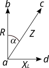
Fig. 2 Impedance vector diagram |
Fig 2 is a vector diagram that shows what is happening. The value in ohms of the trimpot resistance is represented by vector a - b in the vertical direction. The value in ohms of the inductive reactance XL is represented by vector a - d in the horizontal direction. This direction is at 90° to that of R because the effect that an inductor has in a circuit is 90 degrees out of phase with the effect that a resistor has. The resultant impedance Z in ohms is shown by vector a - c and it lies at an angle alpha where tan alpha = XL/R. Knowing R and angle alpha, XL can be calculated The initial fringe created with just trimpot i in circuit results in an interference fringe in direction a - b since there is no component of inductive reactance XL present. If just the inductor g is connected the fringe is in direction a - d.
|
Notes
i) The resistors used in any spin torsion experiment must be non inductive. That is why Bournes linear trimmer potentiometers (trimpots) are used. Normal axial lead resistors have a spiral cut into the resistive material as part of the manufacturing process. This give the resistors a parasitic inductance of around 4nH in addition to their resistance and leads to undesirable inductive reactance.
ii) In order to increase the angular accuracy, distance c - e in figure 1 was around 8.7m. Spin torsion radiation travels unattenuated through walls so the experimental area can encompass more than one room. One problem is that the radiation polarises mass. Although the polarisation fades with time it is probably best to avoid masonry walls with high mass.
iii) Once a measurement was taken the interferometer bars were tilted inwards to alter any interference effects and minimse polarisation. The trimpot was adjusted, the tubes returned to their upright position and another measurement made.
4. Results
| Resistance(KΩ) | Angle α (°) | XL (KΩ) | Table 1. Unscreened trimpot Table 1 shows the result of measurements of phase angle made for various values of resistance. The phase angles were calculated by measuring the distances c - e and c - a in figure 1. To improve the accuracy of the measurement c - e was made as large as practical, in this case 8.71m |
|
|---|---|---|---|---|
| 1000 | 18 | 325 | ||
| 900 | 23.5 | 391 | ||
| 800 | 33.7 | 534 | ||
| 700 | 38.4 | 555 | ||
| 600 | 44.9 | 598 |
In table 1 XL = R tan α and was calculated for various values of resistance. All the calculated values of XL should be the same since the value of the 17.5nH inductance in the circuit was unchanged throughout the experiment. , Table 1 shows XL increasing in a systematic manner and after investigation it was found that the changes in XL in table 1 were caused by torsion fields influencing the trimpot. The trimpot was screened and another set of readings taken.
| Resistance(KΩ) | Angle α (°) | XL (KΩ) | Table 2. Screened trimpot
The results shown in table 2 were taken with both the inductor g and trimpot i in figure 1 screened using a double layer of crossed polyethylene. |
|
|---|---|---|---|---|
| 1000 | 11.4 | 202 | ||
| 900 | 13.1 | 209 | ||
| 800 | 16.7 | 240 | ||
| 700 | 20.0 | 254 | ||
| 600 | 24.0 | 267 |
The calculated values of XL in table 2 are much more constant than the values in table 1 and confirm that the unscreened trimpot used for the table 1 results was indeed being influenced by the incident spin torsion field. However the values for XL in table 2 are still exhibiting some systematic error and it was believed that this was still caused by the effect of spin torsion radiation on the trimpot. Since the trimpot was screened the only source of this radiation was the torsion current through the trimpot. To counteract this a second trimpot was used as shown in figure 3
Fig. 3 Phased array with compensating trimpot |
Figure 3 shows a second trimpot n wired in series with tube j. Additional screening material m and o is also shown around trimpots i and n. Note that screens h and m around inductor g and trimpot i respectively must be individual and not shared. The function of additional trimpot n is to counteract the effect on the calculated value of XL caused by spin torsion current flowing through trimpot i. |

| Resistance(KΩ) | Angle α (°) | XL (KΩ) | Table 3. Compensating trimpot The results shown in table 3 were obtained when a compensating trimpot was used as shown in figure 2. For all measurements both trimpots were adjusted to the same resistance value |
|
|---|---|---|---|---|
| 1000 | 11.3 | 200 | ||
| 900 | 13.6 | 218 | ||
| 800 | 15.3 | 218 | ||
| 700 | 17.8 | 225 | ||
| 600 | 21.6 | 238 |
The calculated values of X L in table 3 are significantly less variable than the values in table 2 and confirm that the addition of a compensating trimpot had a significant effect. There is still some systematic variability but it is believed that this is difficult to fully compensate for because the torsion circuit through tube j cannot be identical to the circuit through tube d because it cannot contain an inductor. The inductor used in the experiment has a tolerance of 5% and measurements of fringe distances can only be made to at best within 10cm. Thus there is already a degree of approximation built into the method. In view of this the value of XL was taken as 200KΩ, the mean of the values for XL in table 3.
4. Spin torsion frequency and propagation speed.
The wavelength of spin torsion radiation has already been determined as 21.1cm. If the radiation had been electromagnetic it would have a frequency f of 1.42GHZ. At this frequency the 17.5nH inductor would have an inductive reactance of 156Ω given by the formulaXL= 2 π f L.
From this experiment the actual value of XL in the spin torsion circuit was 200KΩ - a factor of 1282 greater than 156Ω.
In the formula above for XL, f must be 1282*1.42GHZ = 1.8THZ.
Propagation speed = frequency x wavelength. Since the frequency is 1282 time higher than the frequency expected were the radiation to be electromagnetic, then the speed of propagation must be 1282 times faster than the speed of light.
5. Comments
By investigating the influence of a spin torsion field on an inductor it has been possible to derive some estimates of the propagation speed and frequency of the radiation. The main assumption that has been made is that the equations for the impedance of an inductor hold in a spin torsion circuit. If this is true then spin torsion radiation has many of the characteristics of electromagnetic radiation but with propagation speeds three orders of magnitude greater.
The superluminal speed of spin torsion radiation has also been demonstrated in the experiment on spin torsion radiation from the Sun where radiation from the Sun travels to Earth almost instantaneously. The reader is directed to comments relating to superluminal propagation speeds which can be found in the comments section of that experiment.
| © Neil Duffy 2022 |